Table Of Content
- Understanding the Effects of Airfoil Shape on Lift
- Thermal optimization of shock-induced separation in a natural laminar airfoil operating at off-design conditions
- Numerical Integration of Pressure
- The Advantages of Cambered Airfoils
- Critical Definitions:
- A Complete Guide to Airfoil Shape Considerations
- Effects of Reynolds Number
- Bearhawk 4-Place Aircraft Available With DeltaHawk Engine
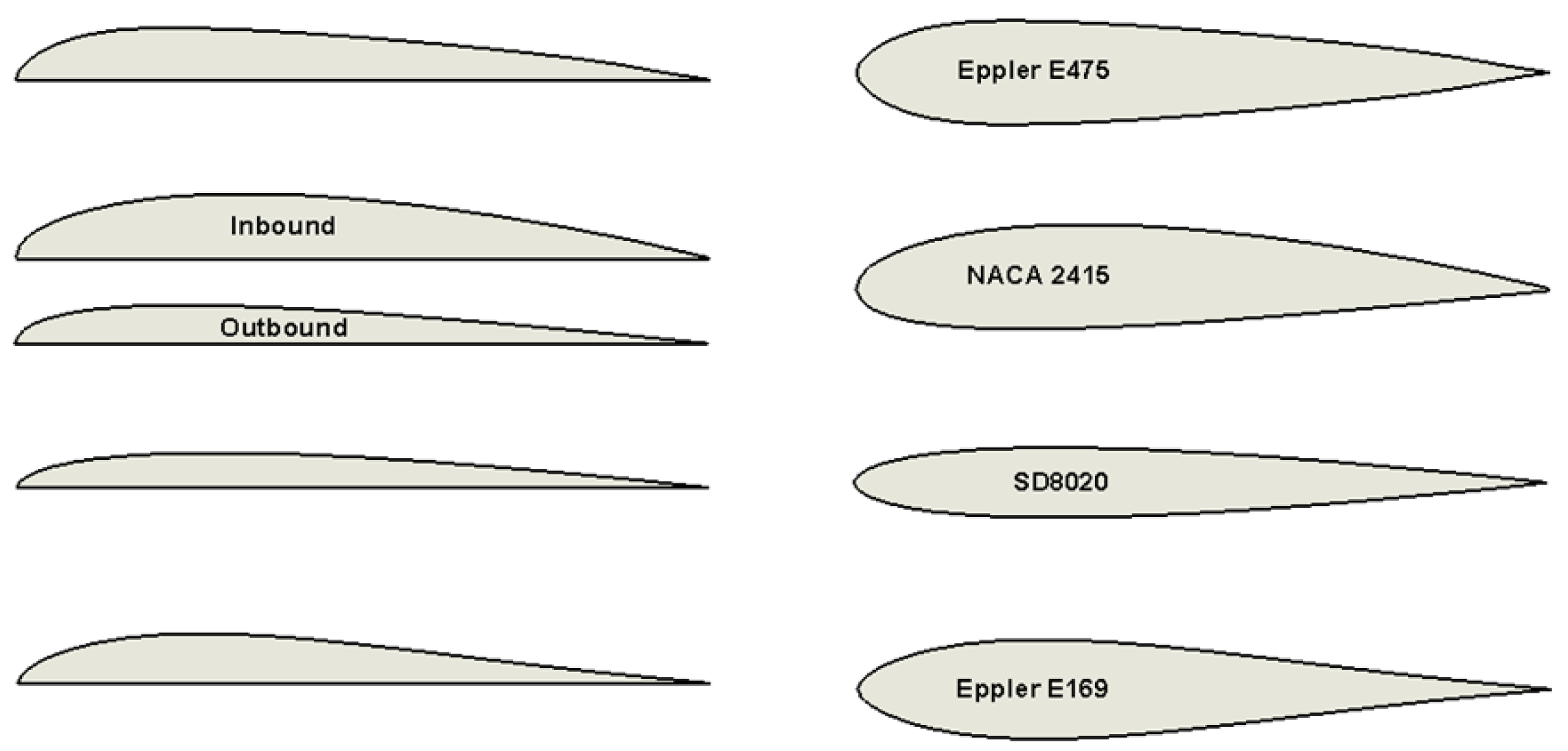
Therefore, it is possible to mimic two-dimensional wings theoretically and experimentally, deriving a better understanding of the aerodynamics of the airfoil section by itself. Comparing this airfoil to the modified NACA of the CH-705 reveals a profile that produces less drag as it's thinner and more streamlined. The airfoil is also less cambered than the NACA which means it produces less lift for a given angle of attack when compared to the CH-750 airfoil. This results in a longer takeoff run as the aircraft needs to be at a higher speed to produce sufficient lift to get airborne.
Understanding the Effects of Airfoil Shape on Lift
If the airplane has flaps, the flap setting is part of its aerodynamic configuration. Riblett built on the works of others, notably Richard Eppler, to come up with his own airfoil designs. The effects of viscosity lead to theformation of the starting vortex (see Figure 4), which, in turn is responsible forproducing the proper conditions for lift. The wings provide lift by creating a situation where the pressure above the wingis lower than the pressure below the wing.
Thermal optimization of shock-induced separation in a natural laminar airfoil operating at off-design conditions
The curve represents an airfoil with a positive camber so some lift is produced at zero angle of attack. With increased angle of attack, lift increases in a roughly linear relation, called the slope of the lift curve. At about 18 degrees this airfoil stalls, and lift falls off quickly beyond that. The drop in lift can be explained by the action of the upper-surface boundary layer, which separates and greatly thickens over the upper surface at and past the stall angle. The thickened boundary layer's displacement thickness changes the airfoil's effective shape, in particular it reduces its effective camber, which modifies the overall flow field so as to reduce the circulation and the lift.
Numerical Integration of Pressure
The variation of the drag with the angle of attack and/or with the lift coefficient is of great interest because of its essential effects on aircraft performance, i.e., the drag generally always acts to diminish the aircraft’s performance. Some representative results are shown in the figure below in terms of drag coefficient versus lift coefficient for both a conventional airfoil (in this case, the NACA 23012) and a so-called “laminar flow” airfoil (a NACA 63-series airfoil). The drag stays low until the angle of attack and the corresponding lift coefficient have increased to the point that significant boundary layer thickening occurs. Pitching moments are defined as positive when the moment tends to increase the angle of attack of the airfoil section, i.e., positive pitching moments are equivalent to nose-up moments.
Often, the moment curve has a shallow positive slope because the aerodynamic center (defined later) is close to but just forward of the 1/4-chord. It should be appreciated that the flow over any wing of finite span will be inherently three-dimensional and further complicated by the effects of the vortices that trail behind the wing, as shown in the figure below. The presence of these vortices produces a downwash flow over the wing, affecting the local angles of attack over the entire wing and, therefore, its lift and overall aerodynamic characteristics. The flow can be assumed nominally two-dimensional only at sections well away from the wing tip vortices. What the graph does show though is that the F-16 is most efficient at high speeds where the lift coefficient is low (high speeds).
Because the value of the lift-curve slope is always positive, the slope of the moment curve defines the sign of position of the aerodynamic center relative to 1/4-chord. So, if this slope is positive, the aerodynamic center is in front of the 1/4-chord; if it is negative, the aerodynamic center is behind the 1/4-chord. For thin airfoils, the value of is almost constant, so the aerodynamic center is generally always close to 1/4-chord at low free-stream Mach numbers. At the highest Reynolds number, the lift coefficient varies almost linearly with the angle of attack, and the drag is nominally constant, which is typical of airfoil behavior at higher Reynolds numbers, as previously discussed. However, as the Reynolds number decreases below a million, the lift and drag curves become much more “rounded” and eventually become significantly nonlinear for variations in the angle of attack. Again, it is essential to recognize that this preceding equation can only represent airfoil characteristics below stall; they are invalid with any significant amounts of flow separation or in the stalled flow regime.
Educator Guide: The Ring Wing Glider - NASA Jet Propulsion Laboratory
Educator Guide: The Ring Wing Glider.
Posted: Fri, 28 Oct 2016 18:43:43 GMT [source]
If this is the first time you used this feature, you will be asked to authorise Cambridge Core to connect with your Google Drive account.Find out more about saving content to Google Drive. To save this article to your Dropbox account, please select one or more formats and confirm that you agree to abide by our usage policies. If this is the first time you used this feature, you will be asked to authorise Cambridge Core to connect with your Dropbox account.Find out more about saving content to Dropbox. All rights are reserved, including those for text and data mining, AI training, and similar technologies. The two types of boundary layers may thus be manipulated to favor these properties.
Harvard Researchers Design Shark-Inspired Airfoil News - Harvard Crimson
Harvard Researchers Design Shark-Inspired Airfoil News.
Posted: Wed, 21 Feb 2018 08:00:00 GMT [source]
Effects of Reynolds Number
While the preceding flow visualization images are interesting and of much value, the resulting forces and moments on the airfoil are also important. The effects of the Mach number and, hence, the compressibility of the flow on the lift curve are shown in the figure below. Typically, flow with a Mach number lower than 0.3 is considered incompressible, and an airfoil will have a lift-curve slope of about per radian or 0.11 per degree. Nevertheless, it can be seen that the lift-curve slope increases quickly at the higher Mach numbers because of the effects of compressibility. Notice also that the maximum lift of the airfoil decreases with increasing Mach number.
Bearhawk 4-Place Aircraft Available With DeltaHawk Engine
Tosatisfy the conservation of angular momentum, there must be an equivalent motion to opposethe vortex movement. The velocity vectors from this counter circulation add to the free flow velocityvectors, thus resulting in a higher velocity above the wing and a lower velocity below thewing (see Figure 6). This latter result shows that the lift-curve slope is lower in supersonic than subsonic flight and decreases with increasing Mach number. In many aerodynamic applications, the 1/4-chord point is used as a reference point, i.e., . The 1/4-chord has theoretical significance, this being the aerodynamic center for a thin airfoil in an incompressible flow. However, even if another reference point were selected, converting from one reference point to another is easy because it is just the application of the rules of statics, as shown in the figure below.
The aerodynamic coefficients are normalized by wing area and dynamic pressure. Lift and drag coefficients are a dimensionless normalization of the amount of lift or drag being produced. We are now going to move from looking at the wing in planform and concentrate on the section profile of the airfoil that is used on the wing. Before we do this we'll start by presenting a few fundamental definitions in order to understand how and why an airfoil is shaped as it is. If you want to learn more about aerodynamics and you’re interested in the subject, here’s a recent Flite Test podcast all about it. The episode features Josh and James and covers Josh Bixler’s approach to designing Flite Test airplanes with aerodynamics in mind.
Maximum lift, pitch moment, drag coefficient, and even airfoil dimensions are changed with just a mouse click and drag. As with landing, it is important to do the evaluation with the flaps in the proper configuration. Most single-engine airplanes take off with the flaps up because they have acceptable takeoff distance and lower drag in this configuration. Regulations vary, so the stall speed must be evaluated in the proper configuration. For example, in the U.S., a single-engine airplane certified under FAR Part 23 is required to have a stall speed no greater than 61 knots in the landing configuration. Landing configuration in this context can include deflected flaps or other high-lift devices.
For example, a composite-skinned wing or a metal-skinned wing with flush riveting can be quite smooth. A metal wing with lap joints between skin panels or rivets with exposed heads can be quite rough. For reasons he can’t explain, Riblett earned a degree in business administration from the University of Delaware. Then he joined the Navy and spent three years in the Mediterranean, directing fighters from the combat information center aboard the USS Des Moines, a heavy cruiser that was the flagship of the Sixth Fleet. Once out of the Navy in 1955, he got married, built a house and started a family. His oldest son, Allen, born in 1954, is a civil engineer in Virginia; Gail, born in 1957, is a lawyer; and Mark, born in 1962, is a mechanical engineer.


No comments:
Post a Comment